The vast majority of PID controllers in service today are digital in nature. Microprocessors executing PID algorithms provide many advantages over any form of analog PID control (pneumatic or electronic), not the least of which being the ability to network with personal computer workstations and other controllers over wired or wireless (radio) networks.
29.13.1 Stand-alone digital controllers
If the internal components of a panel-mounted pneumatic or analog electronic controller (such as the Foxboro models 130 or 62, respectively) were completely removed and replaced by all-digital electronic componentry, the result would be a stand-alone digital PID controller. From the outside, such a digital controller looks very similar its technological ancestors, but its capabilities are far greater.
An example of a popular panel-mounted digital controller is the Siemens model 353 (formerly the Moore Products model 353):
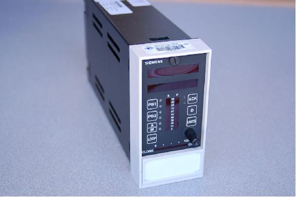
This particular controller, like many high-end digital controllers and larger digital control systems, is programmed in a function block language. Each function block in the controller is a software subroutine performing a specific function on input signals, generating at least one output signal. Each function block has a set of configuration parameters telling it how to behave. For example, the PID function block in a digital controller would have parameters specifying direct or reverse action, gain (Kp), integral time constant (τi), derivative time constant (τd), output limits, etc.
Even the “stock” configuration for simple, single-loop PID control is a collection of function blocks linked together:
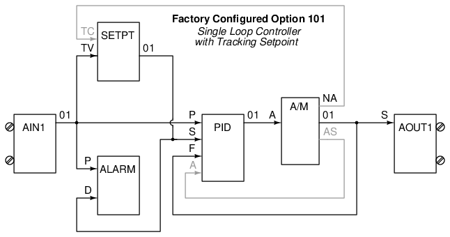
The beauty of function block programming is that the same blocks may be easily re-linked to implement custom control strategies. Take for instance the following function block program written for a Siemens model 353 controller to provide a pulse-width-modulation (PWM, or time-proportioned) output signal instead of the customary 4-20 mA DC analog output signal. The application is for an electric oven temperature control system, where the oven’s heating element could only be turned on and off fully rather than continuously varied:
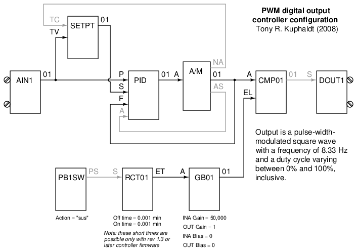
In order to specify links between function blocks, each of the used lettered block inputs is mapped to the output channel of another block. In the case of the time-proportioned function block program, for example, the “P” (process variable) input of the PID function block is set to get its signal from the “01” output channel of the AIN1 (analog input 1) function block. The “TV” (tracking value) input of the SETPT (setpoint) function block is also set to the “01” output channel of the AIN1 function block, so that the setpoint value generator has access to the process variable value in order to implement setpoint tracking. Any function block output may drive an unlimited number of function block inputs (fan-out), but each function block input may receive a signal from only one function block output. This is a rule followed within all function block languages to prevent multiple block output signals from conflicting (attempting to insert different signal values into the same input).
In the Siemens controllers, function block programming may be done by entering configuration data using the front-panel keypad, or by using graphical software running on a personal computer networked with the controller.
For applications not requiring so much capability, and/or requiring a smaller form factor, other panel-mounted digital controllers exist. The Honeywell model UDC3000 is a popular example of a 1/4 DIN (96 mm × 96 mm) size digital controller:
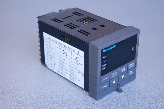
Even smaller panel-mounted controllers are produced by a wide array of manufacturers for applications requiring minimum functionality: 1/8 DIN (96 mm × 48 mm), 1/16 DIN (48 mm × 48 mm), and even 1/32 DIN (48 mm × 24 mm) sizes are available.
One of the advantageous capabilities of modern stand-alone controllers is the ability to exchange data over digital networks. This provides operations and maintenance personnel alike the ability to remotely monitor and even control (adjust setpoints, switch modes, change tuning parameters, etc.) the process controller from a computer workstation. The Siemens model 353 controller (with appropriate options) has the ability to digitally network over Ethernet, a very common and robust digital network standard. The following photographs show three such controllers connected to a network through a common 4-port Ethernet “hub” device:
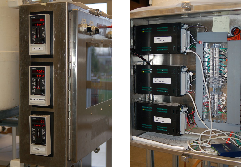
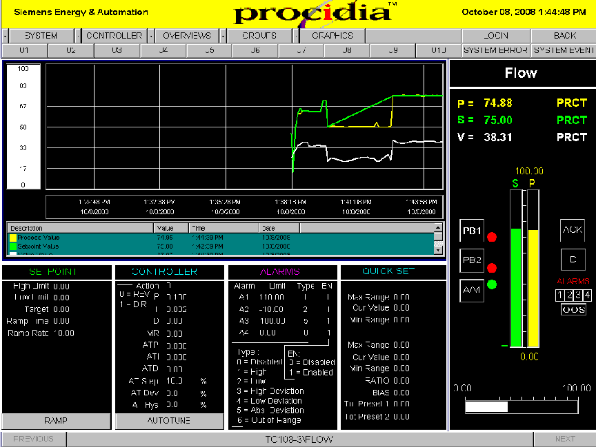
Special software (in this case, Siemens Procidia) running on a computer workstation connected to the same Ethernet network acquires data from and sends data to the networked controllers. Screenshots of this software show typical displays allowing complete control over the function of the process controllers:
29.13.2 Direct digital control (DDC)
A microprocessor operating at sufficient clock speed is able to execute more than one PID control algorithm for a process loop, by “time-sharing” its calculating power: devoting slices of time to the evaluation of each PID equation in rapid succession. This not only makes multiple-loop digital control possible for a single microprocessor, but also makes it very attractive given the microprocessor’s natural ability to manage data archival, transfer, and networking. A single computer is able to execute PID control for multiple loops, and also make that loop control data accessible between loops (for purposes of cascade, ratio, feedforward, and other control strategies) and accessible on networks for human operators and technicians to easily access.
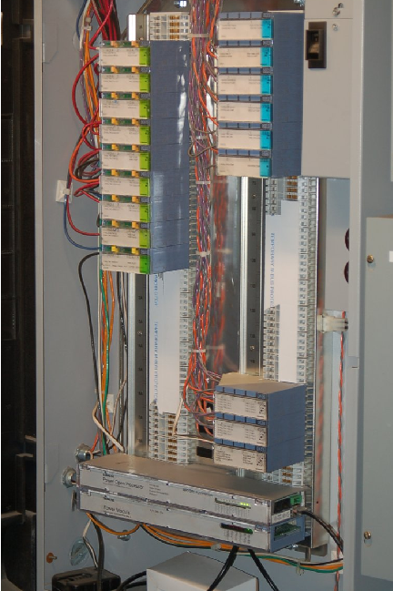
Such direct digital control (DDC) has been applied with great success to the problem of building automation, where temperature and humidity controls for large structures benefit from large-scale data integration. The following photograph shows a Siemens APOGEE building automation system with multiple I/O (input/output) cards providing interface between analog instrument signals and the microprocessor’s digital functions:
A close-up view of an APOGEE processor shows the device handling all mathematical calculations for the PID control:
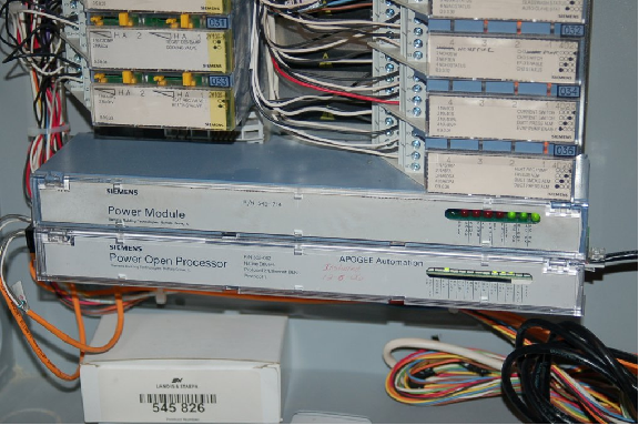
Other than a few LEDs, there is no visual indication in this panel of what the system is doing at any particular time. Operators, engineers, and technicians alike must use software running on a networked personal computer to access data in this control system.
An example of the HMI (Human-Machine Interface) software one might see used in conjunction with a DDC controller is shown here, also from a Siemens APOGEE building control system:
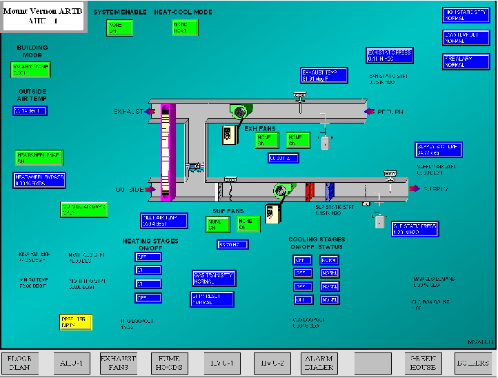
This particular screenshot shows monitored and controlled variables for a heat exchanger (“heat wheel”) used to exchange heat between outgoing and incoming air for the building.
A smaller-scale example of a DDC system is the Delta model DSC-1280 controller, an example shown in the following photograph:
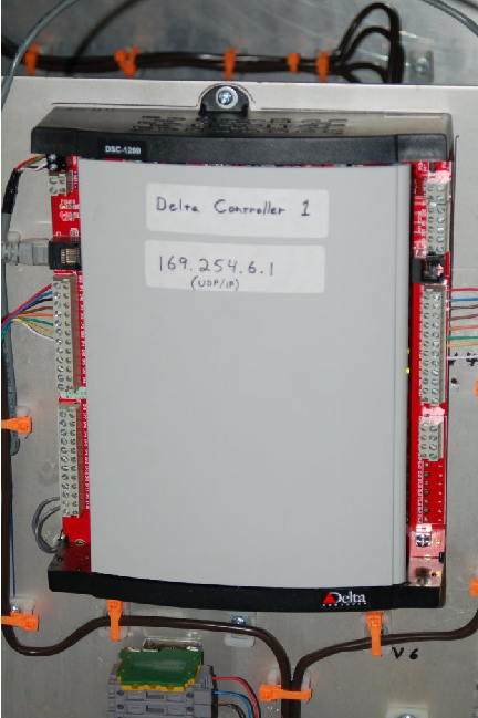
This system does not have plug-in I/O cards like the Siemens APOGEE, but instead is monolithic in design, with all inputs and outputs part of one large “motherboard” PCB. The model DSC-1280 controller has 12 input channels and 8 output channels (hence the model number “1280”). An Ethernet cable (RJ-45 plug) is seen in the upper-left corner of this unit, through which a remotely-located personal computer communicates with the DDC using a high-level protocol called BACnet. In many ways, BACnet is similar to Modbus, residing at layer 7 of the OSI Reference Model (the so-called Application Layer), unconcerned with the details of data communication at the Physical or Data Link layers. This means, like Modbus, BACnet commands may be sent and received over a variety of lower-level network standards, with Ethernet being the preferred32 option at the time of this writing.
Another example of a small-scale DDC is this Distech model ECP-410 unit:
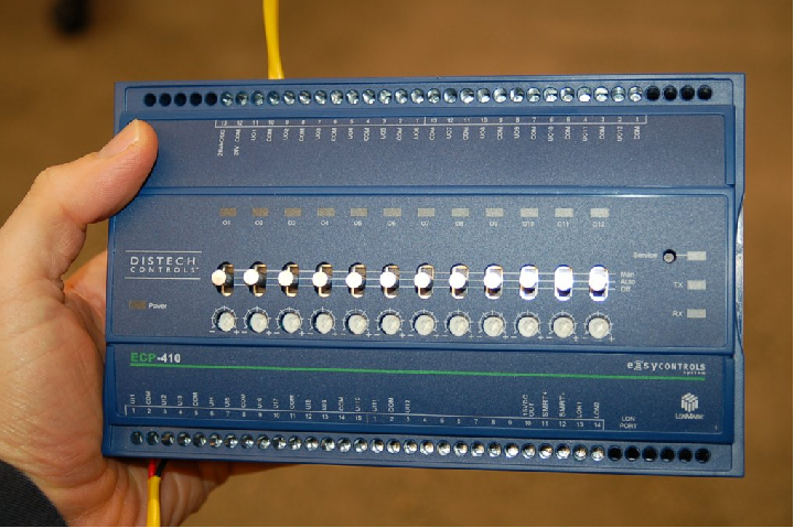
This controller uses LonWorks as its communication protocol rather than BACnet. Like BACnet, LonWorks is an upper-layer protocol and may be transported over Ethernet as well as simpler serial communication formats. The model ECP-410 DDC controller has a two-wire connection for its LonWorks network.
Programming of DDC controllers ranges from text-based languages (similar to BASIC) to function-block programming. The Delta DSC-1280 is an example of a controller programmed in text, while the Distech ECP-410 supports function blocks in addition to text-based programming.
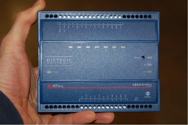
The application-specific nature of DDC (environmental controls for the interior of large buildings and other facilities) lends itself to controller units pre-programmed to perform well-defined tasks rather than general-purpose controllers designed to be user-programmable for any task. An example of such a “fixed” program controller is the Distech model EC-RTU-L, designed to control a “rooftop unit” for air handling:
A more common application of industrial DDC is the use of programmable logic controllers (PLCs) to control multiple loops. PLCs were originally invented for on/off (discrete) process control functions, but have subsequently grown in speed and capability to execute analog PID control functions as well. This next photograph shows an Allen-Bradley (Rockwell) ControlLogix PLC used to control the operation of a gas turbine engine. The PLC may be seen in the upper-left corner of the enclosure, with the rest of the enclosure devoted to terminal blocks and accessory components:
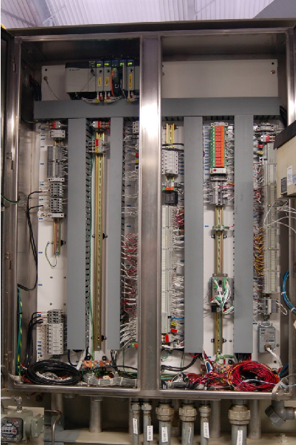
A strong advantage of using PLCs for analog loop control is the ability to easily integrate discrete controls with the analog controls. It is quite easy, for example, to coordinate the sequential start-up and shut-down functions necessary for intermittent operation with the analog PID controls necessary for continuous operation, all within one programmable logic controller. It should be noted, however, that many early PLC implementations of PID algorithms were crude at best, lacking the finesse of stand-alone PID controllers. Even some modern PLC analog functions are mediocre33 at the time of this writing (2008).
29.13.3 SCADA and telemetry systems
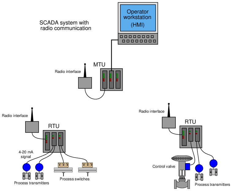
A similar control system architecture to Direct Digital Control (DDC) – assigning a single microprocessor to the task of managing multiple control functions, with digital communication between the microprocessor units – is used for the management of systems which are by their very nature spread over wide geographical regions. Such systems are generally referred to as SCADA, which is an acronym standing for Supervisory Control And Data Acquisition.
The typical SCADA system consists of multiple Remote Terminal Unit (RTU) devices connected to process transmitters and final control elements, implementing basic control functions such as motor start/stop and PID loop control. These RTU devices communicate digitally to a Master Terminal Unit (MTU) device at a central location where human operators may monitor the process and issue commands.
A photograph of an RTU “rack” operating at a large electric power substation is shown here:
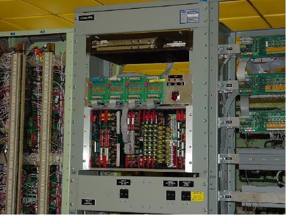
Some RTU hardware, such as the substation monitoring system shown above, is custom-manufactured for the application. Other RTU hardware is more general in purpose, intended for the monitoring and control of natural gas and oil production wells, but applicable to other applications as well.
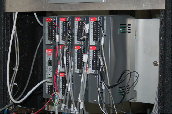
The Fisher ROC 800 – shown in the photograph below – is an example of an RTU designed to operate with a minimum of electrical power, so that a single solar panel and battery will be sufficient for year-round operation in remote environments. The particular unit shown is installed in a natural gas metering station, where is monitors gas pressure, temperature, and flow rate, and also controls the injection of an “odorizing” compound into the gas to give it a bad smell:
Standard programmable logic controllers (PLCs) are ideal candidates for use as RTU devices. Modern PLCs have all the I/O, networking, and control algorithm capability necessary to function as remote terminal units. Commercially available Human-Machine Interface (HMI) software allowing personal computers to display PLC variable values potentially turns every PC into a Master Terminal Unit (MTU) where operators can view process variables, change setpoints, and issue other commands for controlling the process.
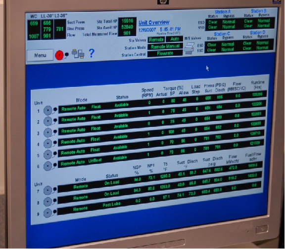
A photograph of such HMI software used to monitor a SCADA system for a set of natural gas compressors is shown here:
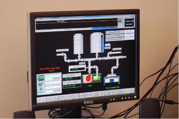
Another photograph of a similar system used to monitor and control drinking water reservoirs for a city is shown here:
A concept closely related to SCADA is that of telemetry, the word literally meaning “distance measuring” (i.e. measuring something over a distance). The acronym SCADA, by containing the word “control,” implies two-way communication (measurement and control) between the master location and the remote location. In applications where the flow of information is strictly one-way (simplex) from the remote location to the master location, “telemetry” is a more apt description.
Telemetry systems find wide application in scientific research. Seismographs, river and stream flowmeters, weather stations, and other remotely-located measurement instruments connected (usually by radio links) to some centralized data collection center are all examples of telemetry. Any industrial measurement (-only) application spanning a large distance could likewise be classified as a telemetry system, although you will sometimes find the term “SCADA” applied even when the communication is simplex in nature.
29.13.4 Distributed Control Systems (DCS)
A radically new concept appeared in the world of industrial control in the mid-1970’s: the notion of distributed digital control. Direct digital control during that era34 suffered a substantial problem: the potential for catastrophic failure if the single digital computer executing multiple PID control functions were to ever halt. Digital control brings many advantages, but it isn’t worth the risk if the entire operation will shut down (or catastrophically fail!) following a hardware or software failure within that one computer.
Distributed control directly addressed this concern by having multiple control computers – each one responsible for only a handful of PID loops – distributed throughout the facility and networked together to share information with each other and with operator display consoles. With individual process control “nodes” scattered throughout the campus, each one dedicated to controlling just a few loops, there would be less concentration of liability as there would be with a single-computer DDC system. Such distribution of computing hardware also shortened the analog signal wiring, because now the hundreds or thousands of analog field instrument cables only had to reach as far as the distributed nodes, not all the way to a centralized control room. Only the networking cable had to reach that far, representing a drastic reduction in wiring needs. Furthermore, distributed control introduced the concept of redundancy to industrial control systems: where digital signal acquisition and processing hardware units were equipped with “spare” units designed to automatically take over all critical functions in the event of a primary failure.
The following illustration shows a typical distributed control system (DCS) architecture:
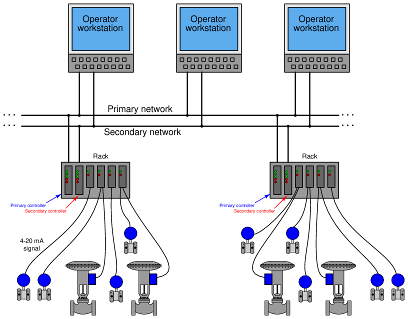
Each “rack” contains a microprocessor to implement all necessary control functions, with individual I/O (input/output) “cards” for converting analog field instrument signals into digital format, and vice-versa. Redundant processors, redundant network cables, and even redundant I/O cards address the possibility of component failure. DCS processors are usually programmed to perform routine self-checks35 on redundant system components to ensure availability of the spare components in the event of a failure.
If there ever was a total failure in one of the “control racks” where the redundancy proved insufficient for the fault(s), the only PID loops faulted will be those resident in that rack, not any of the other loops throughout the system. Likewise, if ever the network cables become severed or otherwise faulted, only the information flow between those two points will suffer; the rest of the system will continue to communicate data normally. Thus, one of the “hallmark” features of a DCS is its tolerance to serious faults: even in the event of severe hardware or software faults, the impact to process control is minimized by design.
One of the very first distributed control systems in the world was the Honeywell TDC2000 system36 , introduced in 1975. By today’s standards, the technology was crude37 , but the concept was revolutionary.
Each rack (called a “box” by Honeywell) consisted of an aluminum frame holding several large printed circuit boards with card-edge connectors. A “basic controller” box appears in the left-hand photograph. The right-hand photograph shows the termination board where the field wiring (4-20 mA) connections were made. A thick cable connected each termination board to its respective controller box:

Controller redundancy in the TDC2000 DCS took the form of a “spare” controller box serving as a backup for up to eight other controller boxes. Thick cables routed all analog signals to this spare controller, so that it would have access to them in the event it needed to take over for a failed controller. The spare controller would become active on the event of any fault in any of the other controllers, including failures in the I/O cards. Thus, this redundancy system provided for processor failures as well as I/O failures. All TDC2000 controllers communicated digitally by means of a dual coaxial cable network known as the “Data Hiway.” The dual cables provided redundancy in network communications.
A typical TDC2000 operator workstation appears in the next photograph:
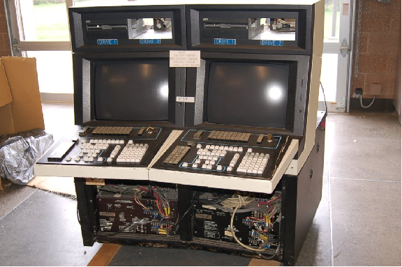
Over the years following its 1975 introduction, the Honeywell system grew in sophistication with faster networks (the “Local Control Network” or LCN), more capable controller racks (the “Process Manager” or PM series), and better operator workstations. Many of these improvements were incremental, consisting of add-on components that could work with existing TDC2000 components so that the entire system need not be replaced to accept the new upgrades.
Other control equipment manufacturers responded to the DCS revolution started by Honeywell and Yokogawa by offering their own distributed control systems. The Bailey Network 90 (Net90) DCS, Bailey Infi90 DCS, and the Fisher Provox systems are examples. Foxboro, already an established leader in the control system field with their SPEC 200 analog system, first augmented the SPEC 200 with digital capabilities (the VIDEOSPEC workstation consoles, FOX I/A computer, INTERSPEC and FOXNET data networks), then developed an entirely digital distributed control system, the SPECTRUM.
Some modern distributed control systems offered at the time of this writing (2008) include:
- ABB 800xA
- Emerson DeltaV and Ovation
- Foxboro (Invensys) I/A
- Honeywell Experion PKS
- Yokogawa CENTUM VP and CENTUM CS
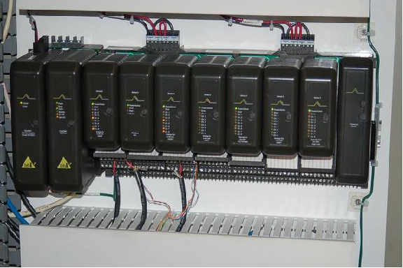
For a visual comparison with the Honeywell TDC2000 DCS, examine the following photograph of an Emerson DeltaV DCS rack, with processor and multiple I/O modules:
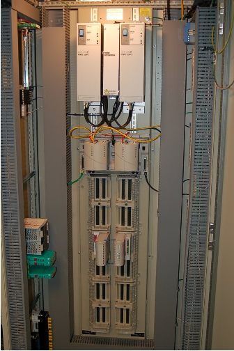
A photograph of an Emerson Ovation DCS rack shows a vertically-oriented backplane accepting multiple I/O modules:
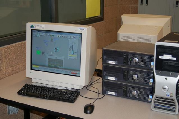
Many modern distributed control systems such as the Emerson DeltaV use regular personal computers rather than proprietary hardware as operator workstations. This cost-saving measure leverages existing computer and display technologies without sacrificing control-level reliability (since the control hardware and software is still industrial-grade):
As previously mentioned in the Direct Digital Control (DDC) subsection, programmable logic controllers (PLCs) are becoming more and more popular as PID control platforms due to their ever-expanding speed, functionality, and relatively low cost. It is now possible with modern PLC hardware and networking capabilities to build a truly distributed control system with individual PLCs as the processing nodes, and with redundancy built into each of those nodes so that any single failure does not interrupt critical control functions. Such a system may be purchased at a fraction of the up-front cost of a fully-fledged DCS.
However, what is currently lacking in the PLC world is the same level of hardware and software integration necessary to build a functional distributed control system that comes as ready-to-use as a system pre-built by a DCS manufacturer. In other words, if an enterprise chooses to build their own distributed control system using programmable logic controllers, they must be prepared to do a lot of programming work in order to emulate the same level of functionality and power as a pre-engineered DCS38 . Any engineer or technician who has experienced the power of a modern DCS – with its self-diagnostic, “smart” instrument management, event auditing, advanced control strategy, pre-engineered redundancy, data collection and analysis, and alarm management capabilities – realizes these features are neither luxuries nor are they trivial to engineer. Woe to anyone who thinks these critical features may be created by incumbent staff at a lesser cost!
29.13.5 Fieldbus control
The DCS revolution started in the mid-1970’s was fundamentally a moving of control system “intelligence” from a centralized location to distributed locations. Rather than have a single computer (or a panel full of single-loop controllers) located in a central control room implement PID control for a multitude of process loops, many (smaller) computers located closer to the process areas would execute the PID and other control functions, with network cables shuttling data between those distributed locations and the central control room.
Beginning in the late 1980’s, the next logical step in this evolution of control architecture saw the relocation of control “intelligence” to the field instruments themselves. In other words, the new idea was to equip individual transmitters and control valve positioners with the necessary computational power to implement PID control all on their own, using digital networks to carry process data between the field instruments and any location desired. This is the fundamental concept of fieldbus.
“Fieldbus” as a technical term has multiple definitions. Many manufacturers use the word “fieldbus” to describe any digital network used to transport data to and from field instruments. In this subsection, I use the word “fieldbus” to describe a design philosophy where field instruments possess all the necessary “intelligence” to control the process, with no need for separate centralized (or even distributed) control hardware. FOUNDATION Fieldbus is the first standard to embody this fully-distributed control concept, the technical details of this open standard maintained and promoted by the Fieldbus Foundation. The aim of this Foundation is to establish an open, technical standard for any manufacturer to follow in the design of their fieldbus instruments. This means a FOUNDATION Fieldbus (FF) transmitter manufactured by Smar will work seamlessly with a FF control valve positioner manufactured by Fisher, communicating effortlessly with a FF-aware host system manufactured by ABB, and so on. This may be thought of in terms of being the digital equivalent of the 3-15 PSI pneumatic signal standard or the 4-20 mA analog electronic signal standard: so long as all instruments “talk” according to the same standard, brands and models may be freely interchanged to build any control system desired.
To illustrate the general fieldbus concept, consider this flow control system:
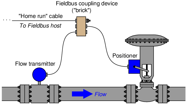
Here, a fieldbus coupling device provides a convenient junction point for cables coming from the transmitter, valve positioner, and host system. FOUNDATION Fieldbus devices both receive DC power and communicate digitally over the same twisted-pair cables. In this case, the host system provides DC power for the transmitter and positioner to function, while communication of process data occurs primarily between the transmitter and positioner (with little necessary involvement of the host system39 ).
As with distributed control systems, FOUNDATION Fieldbus instruments are programmed using a function block language. In this case, we must have an analog input (for the transmitter’s measurement), a PID function block, and an analog output (for the valve positioner) to make a complete flow control system:

The analog input (AI) block must reside in the transmitter, and the analog output (AO) block must reside in the valve positioner, since those blocks necessarily relate to the measured and controlled variables, respectively. However, the PID block may reside in either field device:
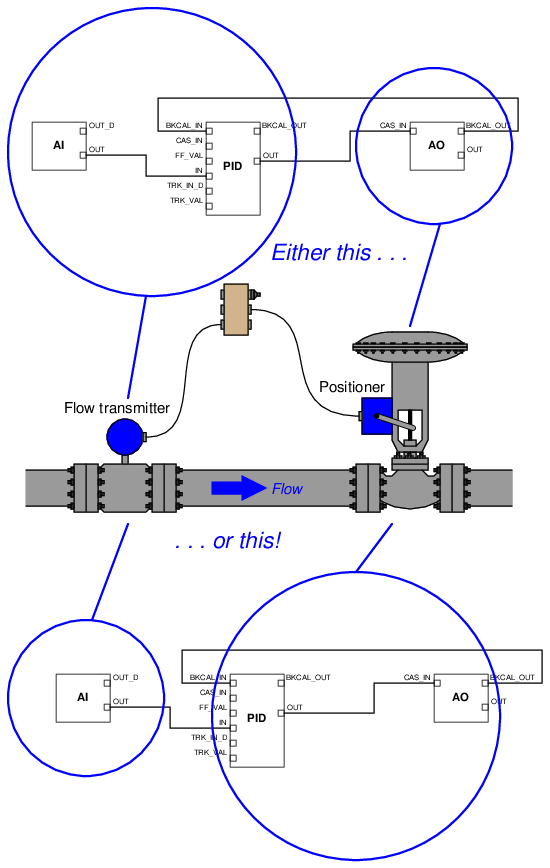
Practical reasons do exist for choosing one location of the PID function block over the other, most notably the difference in communication loading between the two options40 . However, there is no conceptual limitation to the location of the PID function block. In a fieldbus control system where the control “intelligence” is distributed all the way to the field instrument devices themselves, there are no limits to system flexibility.