A design-based fortification is one rooted in technical details of system architecture and functionality. Some of these are quite simple (e.g. air gaps) while others are quite complex (e.g. encryption). In either case, these fortifications are ideally implemented at the inception of a new system, and at every point of system alteration or expansion.
33.4.1 Advanced authentication
The authentication security provided by passwords, which is the most basic and popular form of authentication at the time of this writing, may be greatly enhanced if the system is designed to not just reject incorrect passwords, but to actively inconvenience the user for entering wrong passwords.
Consider for example the following diagram showing a simplified control system network for an industrial facility. Field instruments such as transmitters and control valves connect to I/O (Input/Output) modules directly connected to microprocessor-based controllers. These controllers may be SCADA RTUs (Remote Terminal Units), DCS (Distributed Control System) nodes, PLCs (Programmable Logic Controllers), or any other form of digital system designed to automatically measure and/or control physical processes. Human operators require access to the data collected by these controllers, and also access to parameters necessary for regulation (e.g. setpoint values), which in this case is provided by a set of personal computers called workstations. A separate workstation PC exists for maintenance and engineering use, loaded with appropriate software applications for accessing low-level parameters in the control system nodes and for updating control system software. In this example, Ethernet is the network standard of choice used to link all these devices together for the mutual sharing of data:
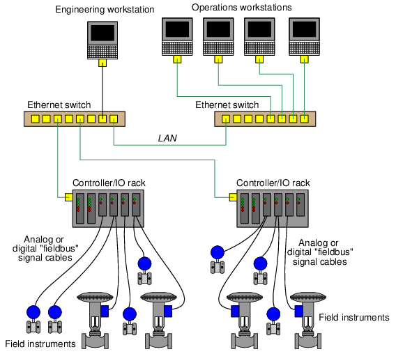
It would be wise to configure the PC workstations with password authentication to ensure only authorized personnel have access to the functions of each. The engineering workstation in particular needs to be protected so that unauthorized personnel do not (either accidently or maliciously) alter critical parameters within the control system essential for proper regulation which could damage the process or otherwise interrupt production.
Password timeout systems introduce a mandatory waiting period for the user if they enter an incorrect password, typically after a couple of attempts so as to allow for innocent entry errors. Password lockout systems completely lock a user out of their digital account if they enter multiple incorrect passwords. The user’s account must then be reset by another user on that system possessing high-level privileges.
The concept behind both password timeouts and password lockouts is to greatly increase the amount of time required for any dictionary-style or brute-force password attack to be successful, and therefore deter these attacks. Unfortunately timeouts and lockouts also present another form of system vulnerability to a denial of service attack. Someone wishing to deny access to a particular system user need only attempt to sign in as that user, using as many incorrect passwords as necessary to trip the automatic lockout. The timeout or lockout system will then delay (or outright deny) access to the legitimate user.
Authentication based on the user’s knowledge (e.g. passwords) is but one form of identification, though. Other forms of authentication exist which are based on the possession of physical items called tokens, as well as identification based on unique features of the user’s body (e.g. retinal patterns, fingerprints, facial features) called biometric authentication.
Token-based authentication requires all users to carry tokens on their person. This form of authentication so long as the token does not become stolen or copied by a malicious party.
Biometric authentication enjoys the advantage of being extremely difficult to replicate and nearly12 impossible to lose. The hardware required to scan fingerprints is relatively simple and inexpensive. Retinal scanners are more complex, but not beyond the reach of organizations possessing expensive digital assets. Presumably, there will even be DNA-based authentication technology available in the future.
33.4.2 Air gaps
An air gap is precisely what the name implies: a physical separation between the critical system network and any other data network preventing communication. Although it seems so simple that it ought to be obvious, an important design question to ask is whether or not the system in question really needs to have connectivity at all. Certainly, the more networked the system is, the easier it will be to access useful information and perform useful operational functions. However, connectivity is also a liability: that same convenience makes it easier for attackers to gain access.
Consider the following diagram, showing a simplified example of an industrial control system network (the Control System Local Area Network, or CS LAN) “air gapped” from the facility’s IT network (the IT LAN):
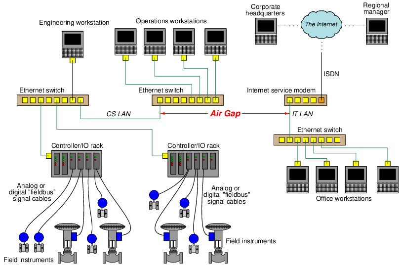
The air gap between the two Ethernet-based networks not only preclude any direct data transfer between one and the other, but also ensure their respective data traffic never collides. This simple design should be used whenever possible, as it is simple and effective on multiple fronts.
While it may seem as though air gaps are the ultimate solution to digital security because they absolutely prohibit direct network-to-network data transfer, they are not invincible. A control system that never connects to a network other than its own is still vulnerable to cyber-attack via detachable programming and data-storage devices. For example, one of the controllers in the example control system may become compromised by way of an infected flash data drive plugged into the Engineering Workstation computer.
In order for air gaps to be completely effective, they must be permanent and include portable devices as well as network connections. This is where effective security policy comes into play, ensuring portable devices are not allowed into areas where they might connect (intentionally or otherwise) to critical systems. Effective air-gapping of critical networks also necessitates physical security of the network media: ensuring attackers cannot gain access to the network cables themselves, so as to “tap” into those cables and thereby gain access. This requires careful planning of cable routes and possibly extra infrastructure (e.g. separate cable trays, conduits, and access-controlled equipment rooms) to implement.
Wireless (radio) data networks pose a special problem for the “air gap” strategy, because the very purpose of radio communication is to bridge physical air gaps. A partial measure applicable to some wireless systems is to use directional antennas to link separated points together, as opposed to omnidirectional antennas which transmit and receive radio energy equally in all directions. This complicates the task of “breaking in” to the data communication channel, although it is not 100 percent effective since no directional antenna has a perfectly focused radiation pattern, nor do directional antennas preclude the possibility of an attacker intercepting communications directly between the two antennae. Like all security measures, the purpose of using directional antennas is to make an attack less probable.
33.4.3 Firewalls
Digital networks should be separated into different areas or layers in order to reduce their exposure to sources of harm. A network “air gap” is an extreme form of network segregation, but is impractical when some data must be communicated between networks.
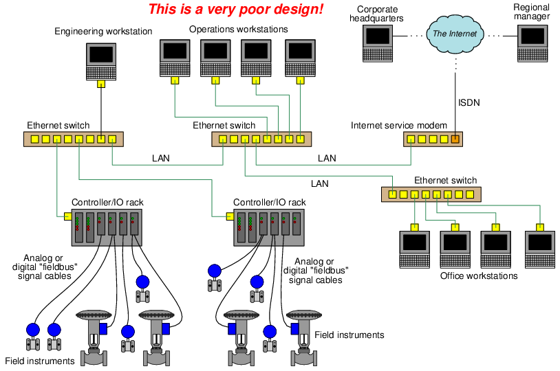
At the opposite end of the network segregation spectrum is a scenario where all digital devices, control systems and office computers alike, connect to the facility’s common Local Area Network (LAN). This is a universally bad policy, as it invites a host of problems not limited to cyber-attacks but extending well beyond that to innocent mistakes and routine faults which may compromise system integrity. At the very least, control systems deserve their own dedicated network(s) on which to communicate, free of traffic from general information technology (IT) office systems. The following illustration shows a very poorly-designed network for an industrial facility, where all computers share a common LAN, and are all connected to the internet:
In facilities where control system data absolutely must be shared on the general LAN, or shared with an external network such as a WAN or the internet, a firewall should be used to connect those two networks. Firewalls are either software or hardware entities designed to filter data passed through based on pre-set rules. These rules are stored in a list called an Access Control List, or ACL. In essence, each network on either side of a firewall is a “zone” of communication, while the firewall is a “conduit” between zones allowing only certain types of messages through. A rudimentary firewall might be configured to “blacklist” any data packets carrying hyper-text transfer protocol (HTTP) messages, as a way to prevent web-based access to the system. Alternatively, a firewall might be configured to “whitelist” only data packets carrying Modbus messages for a control system and block everything else.
Firewalls are standard in IT networks, and have been used successfully for many years. They may exist as discrete hardware devices with multiple network cable jacks (at minimum one in and one out) screening data traffic between two or more LAN segments, or as software applications running under the operating system of a personal computer to screen data traffic in and out of that PC.
A revised version of the previous industrial network diagram shows how a firewall device could be inserted in such a way as to segregate the LAN into two sub-networks, one for the control system and another for general use:
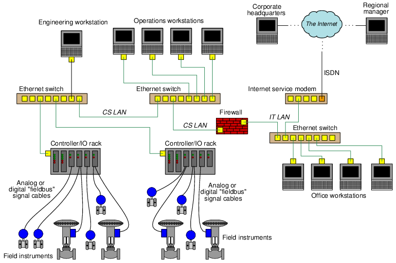
With this firewall in place between the CS and IT networks, and configured with appropriate rules governing the passage of data between the two networks, the control system will be more secure from outside eavesdropping or attack than it was before. For example, data packets received by the firewall from questionable sources on the internet may be denied, while data packets received from known-legitimate sources may be permitted. Certain destination addresses, such as the IP addresses of the controllers themselves, may be blocked from receiving any data originating on the IT LAN, since only the Operations and Engineering workstations should ever need to send data to the controllers.
Similarly, another firewall could be inserted between the IT LAN’s Ethernet switch and the Internet service modem for the purpose of screening data flowing between the IT LAN and the outside world. This would add a measure of security to the facility’s IT network.
Firewall configuration is an area where stark differences may be seen between the control system (CS) versus information technology (IT) worlds. In the IT world, the job of a firewall is to permit passage of an extremely diverse legitimate data traffic while blocking very specific forms of data. In the CS world, most legitimate data is of a very limited type and occurs between a very limited number of devices, while all other data is considered illegitimate. For this reason, it is more common to see IT firewalls employ a “blacklist” policy where all data is permitted except for types specifically blacklisted in the ACL rules, while CS firewalls commonly employ a “whitelist” policy where all data is denied unless specifically permitted in the ACL rules.
For example, below you will see a few “blacklist” rules taken from a typical iptables13 entry for the native firewall within a Linux operating system, intended to reject (“DROP”) any data packets entering the computer from an internet modem connected to Ethernet port 0 (eth0) bearing an IP address within any of the “private” ranges14 specified by the Internet Corporation for Assigned Names and Numbers (ICANN):
iptables -A INPUT -i eth0 -s 10.0.0.0/8 -j DROP
iptables -A INPUT -i eth0 -s 172.16.0.0/12 -j DROP
iptables -A INPUT -i eth0 -s 192.168.0.0/16 -j DROP
The -s option in iptables specifies a source IP address (or range of addresses as shown above), meaning that such a rule is screening data packets based on layer 3 of the OSI Reference model. Firewalls also provide the means to screen data based on TCP ports which exist at layer 4 of the OSI model, as seen in this next example:
iptables -A INPUT -p tcp –dport http -j ACCEPT
iptables -A INPUT -p tcp –dport ssh -j ACCEPT
Here, the -p option (protocol) specifies screening based on TCP port identification, while the –dport (destination port) option specifies which TCP port will be identified. Together, these two rules tell the firewall to permit (“ACCEPT”) all data packets destined for HTTP (web page) or SSH (Secure SHell) ports on external devices, and serve as examples of “whitelist” rules in an ACL.
Basic firewall behavior is based on screening packets based on IP address (either source or destination), and/or based on TCP port, and as such provide only minimal fortification against attack. An example of a crude denial of service attack thwarted by a simple firewall rule is a ping flood. Ping is a network diagnostic utility that is part of the ICMP (Internet Control Message Protocol) suite used to test for connection between two IP-aware devices, and it works by having the receiving device reply to the sending device’s query. These queries and replies are very simple and consist of very small amounts of data, but if a device is repeatedly “pinged” by one or more machines it may become so busy answering ping requests that it cannot do anything else on the network. An example of an ACL rule thwarting this crude attack is as follows:
iptables -A INPUT -p icmp –icmp-type echo-request -j DROP
With this rule in place, the firewall will deny (“DROP”) all echo-request (i.e. ping) queries. This, of course, will prevent anyone from every using ping to diagnose a connection to the firewalled computer, but it will also prevent ping flood attacks.
Many modern firewalls offer stateful inspection of data packets, referring to the firewall’s ability to recognize and log the state of each connection. TCP, for example, uses a “handshaking” procedure involving simple SYN (“synchronize”) and ACK (“acknowledge”) messages sent back and forth between two devices to confirm a reliable connection before any transmitting any data. A stateful firewall will track the progress of this SYN/ACK “handshake” sequence and reject any data from reaching the destination device if they do not agree with the firewall’s logged state of that sequence. Such screening ability filters other types of denial of service attacks which are based on exploitation of this handshake (e.g. a TCP SYN flood attack15 ).
Stateful inspection is only useful, of course, for state-based protocols such as TCP. UDP is a notably stateless protocol that is often used for industrial data because the protocol itself is much simpler than TCP and therefore easier to implement in limited hardware such as within the processor of a PLC.
Some specialized firewalls are manufactured specifically for industrial control systems. One such firewall at the time of this writing (2016) is manufactured by Tofino, and has the capability to screen data packets based on rules specific to industrial control system platforms such as popular PLC models. Industrial firewalls differ from general-purpose data firewalls in their ability to recognize control-specific data, which exists at layer 7 of the OSI Reference model. This is popularly referred to as Deep Packet Inspection, or DPI, because the firewall inspects the contents of each packet (not just source, destination, port, and connection state) for legitimacy.
Two significant challenges complicate Deep Packet Inspection for any industrial control system. The first challenge is that the firewall must be fluent in the control system’s command structure to be able to discern between legitimate and illegitimate data. Thus, DPI firewalls must be pre-loaded with files describing what legitimate control system data and data exchange sequences looks like. Any upgrade of the control system’s network involving changes to the protocol necessitates upgrading of the DPI firewall as well. The second challenge is that the firewall must perform this deep inspection fast enough that the added latency will not compromise control system performance. The more comprehensive the DPI algorithm, the longer each message will be delayed by the inspection, and the slower the network will be.
33.4.4 Demilitarized Zones
For all its complexity, a network firewall really only provides limited security in limiting data communication between two networks. This is especially true of stateless firewalls which only screen data based on such criteria as IP addresses and TCP ports. One way to augment the effectiveness of firewalls is to use multiple firewalls to build something referred to as a DeMilitarized Zone, or DMZ. A DMZ consists of three basic elements: a data server or proxy computer sandwiched between two firewalls. The purpose of a DMZ is to force all data traffic between the segregated networks to pass through the server/proxy device and prohibit any form of direct network-to-network communication. Meanwhile, the server/proxy device is programmed with limited functionality to only process legitimate data between the two networks.
An example of a DMZ applied to our industrial control system appears in the following diagram. Please note that the two firewall symbols shown here merely represent firewall functions and need not exist as two physical devices. It is possible to build a DMZ using a single special-purpose device with multiple Ethernet ports and dual firewall ACLs:
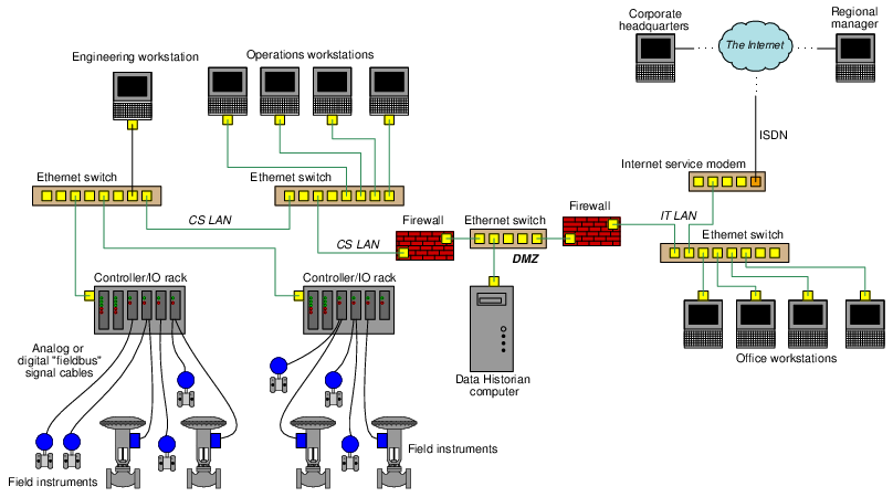
For each firewall at the boundary of the DMZ, its respective ACL must be configured so as to only permit (“whitelist”) the Data Historian computer, which is the “server” device within the DMZ. The purpose of a Data Historian is to poll process data from the control system at regular intervals, store that data on a high-capacity data drive, and provide that data (i.e. “serve the data”) to external computers16 requesting it.
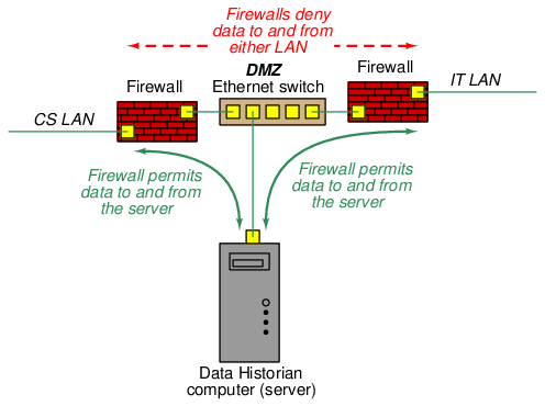
Given the fact that it’s highly unlikely anyone in a corporate office needs access to real-time process data, the Data Historian’s function17 will be limited to polling and archiving process data over long periods of time, typically years. This data, when requested by any user on the IT LAN or beyond, will be provided in convenient form by the Data Historian without need for direct reading from the controllers. One way to view the function of a server inside of a DMZ is to see it as an intentional man-in-the-middle who dispenses information strictly on a need-to-know basis.
A DMZ installed in an IT network must convey a much broader range of information, everything from email messages and web pages to large document files and bandwidth-intensive streaming video. A corporation’s web server, for example, which is the computer upon which web page files are hosted for view by the outside world, is typically located within a DMZ network.
Any cyber-attack on a system shielded behind a DMZ must first compromise one or more of the devices lying within the DMZ before any assault may be launched against the protected network, since the dual firewalls prohibit any direct network-to-network communication. This naturally complicates the task (though, as with any fortification, it can never prevent a breach) for the attacker. The DMZ device’s security therefore becomes an additional layer of protection to whatever fortifications exist within the protected LAN.
33.4.5 Encryption
Encryption refers to the intentional scrambling of data by means of a designated code called a key, a similar (or in some cases identical) key being used to un-scramble (decrypt) that data on the receiving end. The purpose of encryption, of course, is to foil passive attacks by making the data unintelligible to anyone but the intended recipient, and also to foil active attacks by making it impossible for an attacker’s transmitted message to be successfully received.
The strength of any encryption method lies in the key used to encrypt and decrypt the protected data, and so these keys should be managed with similar care as passwords. If the key becomes known to anyone other than the intended users, the encryption becomes worthless. It is for this reason that many encryption systems provide the feature of key rotation, whereby keys are periodically randomized. Just prior to switching to a new key, the new key’s value is communicated with all other devices in the cryptographic system as a piece of encrypted data.
A popular form of encrypted communication is a Virtual Private Network or VPN. This is where two or more devices use VPN software (or multiple VPN hardware devices) to encrypt messages sent to each other over an unsecure network. Since the data exchanged between the two computers is encrypted, the communication will be unintelligible to anyone else who might eavesdrop on that unsecure network. In essence, VPNs create a secure “tunnel” for data to travel between points on an otherwise unprotected network.
A popular use for VPN is securing remote access18 to corporate networks, such as when business executives, salespersons, and engineers must do work while away from the facility site. By “tunneling” through to the company network via VPN, all communications between the employee’s personal computer and the device(s) on the other end are unintelligible to eavesdroppers.
IP-based networks implement VPN tunneling by using an extension of the IP standard called IPsec (IP security), which works by encrypting the original IP packet payload and then encapsulating that encrypted data as the payload of a new (larger) IP packet. In its strongest form IPsec not only encrypts the original payload but also the original IP header which contains information on IP source and destination addresses. This means any eavesdropping on the IPsec packet will reveal nothing about the original message, where it came from, or where it’s going.
Encryption may also be applied to non-broadcast networks such as telephone channels and serial data communication lines. Special cryptographic modems and serial data translators are manufactured specifically for this purpose, and may be applied to legacy SCADA and telemetry networks using on telephony or serial communication cables.
It should be noted that encryption does not necessarily protect against so-called replay attacks, where the attacker records a communicated message and later re-transmits that same message to the network. For example, if a control system uses an encrypted message to command a remotely-located valve to shut, an attacker might simply re-play that same message at any time in the future to force the valve to shut without having to decrypt the message. So long as the encryption key has not changed between the time of message interception and the time of message re-play, the re-played message should be interpreted by the receiving device the same as before, to the same effect. Key rotation therefore becomes an important element in fortifying simplex messages against replay attacks, because a new key will necessarily alter the message from what it was before and thereby render the old (intercepted) message meaningless.
An interesting form of encryption applicable to certain wireless (radio) data networks is spread-spectrum communication. This is where radio communication occurs over a range of different frequencies rather than on a single frequency. Various techniques exist for spreading digital data across a spectrum of radio frequencies, but they all comprise a form of data encryption because the spreading of that data is orchestrated by means of a cryptographic key. Perhaps the simplest spread-spectrum method to understand is frequency-hopping or channel-hopping, where the transmitters and receivers both switch frequencies on a keyed schedule. Any receiver uninformed by the same key will not “know” which channels will be used, or in what order, and therefore will be unable to intercept anything but isolated pieces of the communicated data. Spread-spectrum technology was invented during the second World War as a means for Allied forces to encrypt their radio transmissions such that Axis forces could not interpret them.
Spread-spectrum capability is built into several wireless data communication standards, including Bluetooth and WirelessHART.
Network communication is not the only form of data subject to encryption. Static files stored on computer drives may also be encrypted, such that only users possessing the proper key(s) may decrypt and use the files. This fortification is especially useful for securing data stored on portable media such as flash memory drives, which may easily fall into malevolent hands.
33.4.6 Read-only system access
One way to thwart so-called “active” attacks (where the attacker inserts or modifies data in a digital system to achieve malicious ends) is to engineer the system in such a way that all communicated data is read-only and therefore cannot be written or edited by anyone. This, of course, by itself will do nothing to guard against “passive” (read-only) attacks such as eavesdropping, but passive attacks are definitely the lesser of the two evils with regard to industrial control systems.
In systems where the digital data is communicated serially using protocols such as EIA/TIA-232, read-only access may be ensured by simply disconnecting one of the wires in the EIA/TIA-232 cable. By disconnecting the wire leading to the “receive data” pin of the critical system’s EIA/TIA-232 serial port, that system cannot receive external data but may only transmit data. The same is true for EIA/TIA-485 serial communications where “transmit” and “receive” connection pairs are separate.
Certain serial communication schemes are inherently simplex (i.e. one-way communication) such as EIA/TIA-422. If this is an option supported by the digital system in question, the use of that option will be an easy way to ensure remote read-only access.
For communication standards such as Ethernet which are inherently duplex (bi-directional), devices called data diodes may be installed to ensure read-only access. The term “data diode” invokes the functionality of a semiconductor rectifying diode, which allows the passage of electric current in one direction only. Instead of blocking reverse current flow, however, a “data diode” blocks reverse information flow.
The principle of read-only protection applies to computing systems as well as communication networks. Some digital systems do not strictly require on-board data collection or modification of operating parameters, and in such cases it is possible to replace read/write magnetic data drives with read-only (e.g. optical disk) drives in order to create a system that cannot be compromised. Admittedly, applications of this strategy are limited, as there are few control systems which never store operational data nor require any editing of parameters. However, this strategy should be considered where it applies19 .
Many digital devices offer write-protection features in the form of a physical switch or key-lock preventing data editing. Just as some types of removable data drives have a “write-protect” tab or switch located on them, some “smart” field instruments also have write-protect switches inside their enclosures which may be toggled only by personnel with direct physical access to the device. Programmable Logic Controllers (PLCs) often have a front-panel write-protect switch allowing protection of the running program.
Not only do write-protect switches guard against malicious attacks, but they also help prevent innocent mistakes from causing major problems in control systems. Consider the example of a PLC network where each PLC connected to a common data network has its own hardware write-protect switch. If a technician or engineer desires to edit the program in one of these PLCs from their remotely-located personal computer, that person must first go to the location of that PLC and disable its write protection. While this may be seen as an inconvenience, it ensures that the PLC programmer will not mistakenly access the wrong PLC from their office-located personal computer, which is especially easy to do if the PLCs are similarly labeled on the network.
Making regular use of such features is a policy measure, but ensuring the exclusive use of equipment with this feature is a system design measure.
33.4.7 Control platform diversity
In control and safety systems utilizing redundant controller platforms, an additional measure of security is to use different models of controller in the redundant array. For example, a redundant control or safety system using two-out-of-three voting (2oo3) between three controllers might use controllers manufactured by three different vendors, each of those controllers running different operating systems and programmed using different editing software. This mitigates against device-specific attacks, since no two controllers in the array should have the exact same vulnerabilities.
A less-robust approach to process control security through diverse platforms is simply the use of effective Safety Instrumented Systems (SIS) applied to critical processes, which always employ controls different from the base-layer control system. An SIS system is designed to bring the process to a safe (shut down) condition in the event that the regular control system is unable to maintain normal operating conditions. In order to avoid common-cause failures, the SIS must be implemented on a control platform independent from the regular control system. The SIS might even employ analog control technology (and/or discrete relay-based control technology) in order to give it complete immunity from digital attacks.
In either case, improving security through the use of multiple, diverse control systems is another example of the defense in depth philosophy in action: building the system in such a way that no essential function depends on a single layer or single element, but rather multiple layers exist to ensure that essential function.