A stepper motor is a “digital” version of the electric motor. The rotor moves in discrete steps as commanded, rather than rotating continuously like a conventional motor. When stopped but energized, a stepper (short for stepper motor) holds its load steady with a holding torque. Wide spread acceptance of the stepper motor within the last two decades was driven by the ascendancy of digital electronics. Modern solid state driver electronics was a key to its success. And, microprocessors readily interface to stepper motor driver circuits.
Application wise, the predecessor of the stepper motor was the servo motor. Today this is a higher cost solution to high performance motion control applications. The expense and complexity of a servomotor is due to the additional system components: position sensor and error amplifier. (Figure below) It is still the way to position heavy loads beyond the grasp of lower power steppers. High acceleration or unusually high accuracy still requires a servo motor. Otherwise, the default is the stepper due to low cost, simple drive electronics, good accuracy, good torque, moderate speed, and low cost.

Stepper motor vs servo motor.
A stepper motor positions the read-write heads in a floppy drive. They were once used for the same purpose in harddrives. However, the high speed and accuracy required of modern harddrive head positioning dictates the use of a linear servomotor (voice coil).
The servo amplifier is a linear amplifier with some difficult to integrate discrete components. A considerable design effort is required to optimize the servo amplifier gain vs phase response to the mechanical components. The stepper motor drivers are less complex solid state switches, being either “on” or “off”. Thus, a stepper motor controller is less complex and costly than a servo motor controller.
Slo-syn synchronous motors can run from AC line voltage like a single-phase permanent-capacitor induction motor. The capacitor generates a 90o second phase. With the direct line voltage, we have a 2-phase drive. Drive waveforms of bipolar (±) square waves of 2-24V are more common these days. The bipolar magnetic fields may also be generated from unipolar (one polarity) voltages applied to alternate ends of a center tapped winding. (Figure below) In other words, DC can be switched to the motor so that it sees AC. As the windings are energized in sequence, the rotor synchronizes with the consequent stator magnetic field. Thus, we treat stepper motors as a class of AC synchronous motor.

Unipolar drive of center tapped coil at (b), emulates AC current in single coil at (a).
Characteristics
Stepper motors are rugged and inexpensive because the rotor contains no winding slip rings, or commutator. The rotor is a cylindrical solid, which may also have either salient poles or fine teeth. More often than not the rotor is a permanent magnet. Determine that the rotor is a permanent magnet by unpowered hand rotation showing detent torque, torque pulsations. Stepper motor coils are wound within a laminated stator, except for can stack construction. There may be as few as two winding phases or as many as five. These phases are frequently split into pairs. Thus, a 4-pole stepper motor may have two phases composed of in-line pairs of poles spaced 90o apart. There may also be multiple pole pairs per phase. For example a 12-pole stepper has 6-pairs of poles, three pairs per phase.
Since stepper motors do not necessarily rotate continuously, there is no horsepower rating. If they do rotate continuously, they do not even approach a sub-fractional hp rated capability. They are truly small low power devices compared to other motors. They have torque ratings to a thousand in-oz (inch-ounces) or ten n-m (newton-meters) for a 4 kg size unit. A small “dime” size stepper has a torque of a hundredth of a newton-meter or a few inch-ounces. Most steppers are a few inches in diameter with a fraction of a n-m or a few in-oz torque. The torque available is a function of motor speed, load inertia, load torque, and drive electronics as illustrated on the speed vs torque curve. (Figure below) An energized, holding stepper has a relatively high holding torque rating. There is less torque available for a running motor, decreasing to zero at some high speed. This speed is frequently not attainable due to mechanical resonance of the motor load combination.
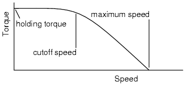
Stepper speed characteristics.
Stepper motors move one step at a time, the step angle, when the drive waveforms are changed. The step angle is related to motor construction details: number of coils, number of poles, number of teeth. It can be from 90o to 0.75o, corresponding to 4 to 500 steps per revolution. Drive electronics may halve the step angle by moving the rotor in half-steps.
Steppers cannot achieve the speeds on the speed torque curve instantaneously. The maximum start frequency is the highest rate at which a stopped and unloaded stepper can be started. Any load will make this parameter unattainable. In practice, the step rate is ramped up during starting from well below the maximum start frequency. When stopping a stepper motor, the step rate may be decreased before stopping.
The maximum torque at which a stepper can start and stop is the pull-in torque. This torque load on the stepper is due to frictional (brake) and inertial (flywheel) loads on the motor shaft. Once the motor is up to speed, pull-out torque is the maximum sustainable torque without losing steps.
There are three types of stepper motors in order of increasing complexity: variable reluctance, permanent magnet, and hybrid. The variable reluctance stepper has s solid soft steel rotor with salient poles. The permanent magnet stepper has a cylindrical permanent magnet rotor. The hybrid stepper has soft steel teeth added to the permanent magnet rotor for a smaller step angle.
Variable reluctance stepper
A variable reluctance stepper motor relies upon magnetic flux seeking the lowest reluctance path through a magnetic circuit. This means that an irregularly shaped soft magnetic rotor will move to complete a magnetic circuit, minimizing the length of any high reluctance air gap. The stator typically has three windings distributed between pole pairs , the rotor four salient poles, yielding a 30o step angle.(Figure below) A de-energized stepper with no detent torque when hand rotated is identifiable as a variable reluctance type stepper.

Three phase and four phase variable reluctance stepper motors.
The drive waveforms for the 3-φ stepper can be seen in the “Reluctance motor” section. The drive for a 4-φ stepper is shown in Figure below. Sequentially switching the stator phases produces a rotating magnetic field which the rotor follows. However, due to the lesser number of rotor poles, the rotor moves less than the stator angle for each step. For a variable reluctance stepper motor, the step angle is given by:
        ΘS = 360o/NS
        ΘR = 360o/NR
        ΘST = ΘR - ΘS
        where: ΘS = stator angle, ΘR = Rotor angle, ΘST = step angle NS = number stator poles, NP = number rotor poles
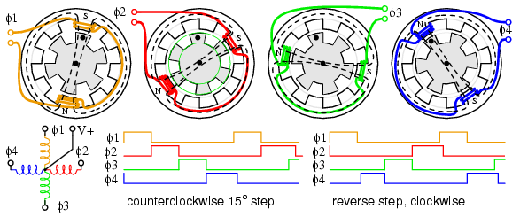
Stepping sequence for variable reluctance stepper.
In Figure above, moving from φ1 to φ2, etc., the stator magnetic field rotates clockwise. The rotor moves counterclockwise (CCW). Note what does not happen! The dotted rotor tooth does not move to the next stator tooth. Instead, the φ2 stator field attracts a different tooth in moving the rotor CCW, which is a smaller angle (15o) than the stator angle of 30o. The rotor tooth angle of 45o enters into the calculation by the above equation. The rotor moved CCW to the next rotor tooth at 45o, but it aligns with a CW by 30o stator tooth. Thus, the actual step angle is the difference between a stator angle of 45o and a rotor angle of 30o . How far would the stepper rotate if the rotor and stator had the same number of teeth? Zero– no notation.
Starting at rest with phase φ1 energized, three pulses are required (φ2, φ3, φ4) to align the “dotted” rotor tooth to the next CCW stator Tooth, which is 45o. With 3-pulses per stator tooth, and 8-stator teeth, 24-pulses or steps move the rotor through 360o.
By reversing the sequence of pulses, the direction of rotation is reversed above right. The direction, step rate, and number of steps are controlled by a stepper motor controller feeding a driver or amplifier. This could be combined into a single circuit board. The controller could be a microprocessor or a specialized integrated circuit. The driver is not a linear amplifier, but a simple on-off switch capable of high enough current to energize the stepper. In principle, the driver could be a relay or even a toggle switch for each phase. In practice, the driver is either discrete transistor switches or an integrated circuit. Both driver and controller may be combined into a single integrated circuit accepting a direction command and step pulse. It outputs current to the proper phases in sequence.
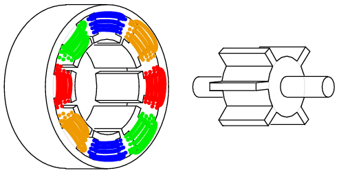
Variable reluctance stepper motor.
Disassemble a reluctance stepper to view the internal components. Otherwise, we show the internal construction of a variable reluctance stepper motor in Figure above. The rotor has protruding poles so that they may be attracted to the rotating stator field as it is switched. An actual motor, is much longer than our simplified illustration.
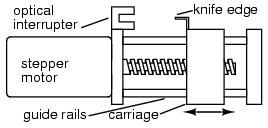
Variable reluctance stepper drives lead screw.
The shaft is frequently fitted with a drive screw. (Figure above) This may move the heads of a floppy drive upon command by the floppy drive controller.
Variable reluctance stepper motors are applied when only a moderate level of torque is required and a coarse step angle is adequate. A screw drive, as used in a floppy disk drive is such an application. When the controller powers-up, it does not know the position of the carriage. However, it can drive the carriage toward the optical interrupter, calibrating the position at which the knife edge cuts the interrupter as “home”. The controller counts step pulses from this position. As long as the load torque does not exceed the motor torque, the controller will know the carriage position.
Summary: variable reluctance stepper motor
- The rotor is a soft iron cylinder with salient (protruding) poles.
- This is the least complex, most inexpensive stepper motor.
- The only type stepper with no detent torque in hand rotation of a de-energized motor shaft.
- Large step angle
- A lead screw is often mounted to the shaft for linear stepping motion.
Permanent magnet stepper
A permanent magnet stepper motor has a cylindrical permanent magnet rotor. The stator usually has two windings. The windings could be center tapped to allow for a unipolar driver circuit where the polarity of the magnetic field is changed by switching a voltage from one end to the other of the winding. A bipolar drive of alternating polarity is required to power windings without the center tap. A pure permanent magnet stepper usually has a large step angle. Rotation of the shaft of a de-energized motor exhibits detent torque. If the detent angle is large, say 7.5o to 90o, it is likely a permanent magnet stepper rather than a hybrid stepper (next subsection).
Permanent magnet stepper motors require phased alternating currents applied to the two (or more) windings. In practice, this is almost always square waves generated from DC by solid state electronics. Bipolar drive is square waves alternating between (+) and (-) polarities, say, +2.5 V to -2.5 V. Unipolar drive supplies a (+) and (-) alternating magnetic flux to the coils developed from a pair of positive square waves applied to opposite ends of a center tapped coil. The timing of the bipolar or unipolar wave is wave drive, full step, or half step.
Wave drive

PM wave drive sequence (a) φ1+ , (b) φ2+ , (c) φ1– , (d) φ2-.
Conceptually, the simplest drive is wave drive. (Figure above) The rotation sequence left to right is positive φ-1 points rotor north pole up, (+) φ-2 points rotor north right, negative φ-1 attracts rotor north down, (-) φ-2 points rotor left. The wave drive waveforms below show that only one coil is energized at a time. While simple, this does not produce as much torque as other drive techniques.

Waveforms: bipolar wave drive.
The waveforms (Figure above) are bipolar because both polarities , (+) and (-) drive the stepper. The coil magnetic field reverses because the polarity of the drive current reverses.

Waveforms: unipolar wave drive.
The (Figure above) waveforms are unipolar because only one polarity is required. This simplifies the drive electronics, but requires twice as many drivers. There are twice as many waveforms because a pair of (+) waves is required to produce an alternating magnetic field by application to opposite ends of a center tapped coil. The motor requires alternating magnetic fields. These may be produced by either unipolar or bipolar waves. However, motor coils must have center taps for unipolar drive.
Permanent magnet stepper motors are manufactured with various lead-wire configurations. (Figure below)

Stepper motor wiring diagrams.
The 4-wire motor can only be driven by bipolar waveforms. The 6-wire motor, the most common arrangement, is intended for unipolar drive because of the center taps. Though, it may be driven by bipolar waves if the center taps are ignored. The 5-wire motor can only be driven by unipolar waves, as the common center tap interferes if both windings are energized simultaneously. The 8-wire configuration is rare, but provides maximum flexibility. It may be wired for unipolar drive as for the 6-wire or 5-wire motor. A pair of coils may be connected in series for high voltage bipolar low current drive, or in parallel for low voltage high current drive.
A bifilar winding is produced by winding the coils with two wires in parallel, often a red and green enamelled wire. This method produces exact 1:1 turns ratios for center tapped windings. This winding method is applicable to all but the 4-wire arrangement above.
Full step drive
Full step drive provides more torque than wave drive because both coils are energized at the same time. This attracts the rotor poles midway between the two field poles. (Figure below)
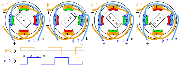
Full step, bipolar drive.
Full step bipolar drive as shown in Figure above has the same step angle as wave drive. Unipolar drive (not shown) would require a pair of unipolar waveforms for each of the above bipolar waveforms applied to the ends of a center tapped winding. Unipolar drive uses a less complex, less expensive driver circuit. The additional cost of bipolar drive is justified when more torque is required.
Half step drive
The step angle for a given stepper motor geometry is cut in half with half step drive. This corresponds to twice as many step pulses per revolution. (Figure below) Half stepping provides greater resolution in positioning of the motor shaft. For example, half stepping the motor moving the print head across the paper of an inkjet printer would double the dot density.
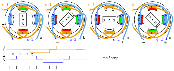
Half step, bipolar drive.
Half step drive is a combination of wave drive and full step drive with one winding energized, followed by both windings energized, yielding twice as many steps. The unipolar waveforms for half step drive are shown above. The rotor aligns with the field poles as for wave drive and between the poles as for full step drive.
Microstepping is possible with specialized controllers. By varying the currents to the windings sinusoidally many microsteps can be interpolated between the normal positions.
Construction
The contruction of a permanent magnet stepper motor is considerably different from the drawings above. It is desirable to increase the number of poles beyond that illustrated to produce a smaller step angle. It is also desirable to reduce the number of windings, or at least not increase the number of windings for ease of manufacture.
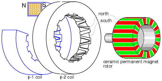
Permanent magnet stepper motor, 24-pole can-stack construction.
The permanent magnet stepper (Figure above) only has two windings, yet has 24-poles in each of two phases. This style of construction is known as can stack. A phase winding is wrapped with a mild steel shell, with fingers brought to the center. One phase, on a transient basis, will have a north side and a south side. Each side wraps around to the center of the doughnut with twelve interdigitated fingers for a total of 24 poles. These alternating north-south fingers will attract the permanent magnet rotor. If the polarity of the phase were reversed, the rotor would jump 360o/24 = 15o. We do not know which direction, which is not usefull. However, if we energize φ-1 followed by φ-2, the rotor will move 7.5o because the φ-2 is offset (rotated) by 7.5o from φ-1. See below for offset. And, it will rotate in a reproducible direction if the phases are alternated. Application of any of the above waveforms will rotate the permanent magnet rotor.
Note that the rotor is a gray ferrite ceramic cylinder magnetized in the 24-pole pattern shown. This can be viewed with magnet viewer film or iron filings applied to a paper wrapping. Though, the colors will be green for both north and south poles with the film.
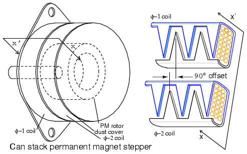
(a) External view of can stack, (b) field offset detail.
Can-stack style construction of a PM stepper is distinctive and easy to identify by the stacked “cans”. (Figure above) Note the rotational offset between the two phase sections. This is key to making the rotor follow the switching of the fields between the two phases.
Summary: permanent magnet stepper motor
- The rotor is a permanent magnet, often a ferrite sleeve magnetized with numerous poles.
- Can-stack construction provides numerous poles from a single coil with interleaved fingers of soft iron.
- Large to moderate step angle.
- Often used in computer printers to advance paper.
Hybrid stepper motor
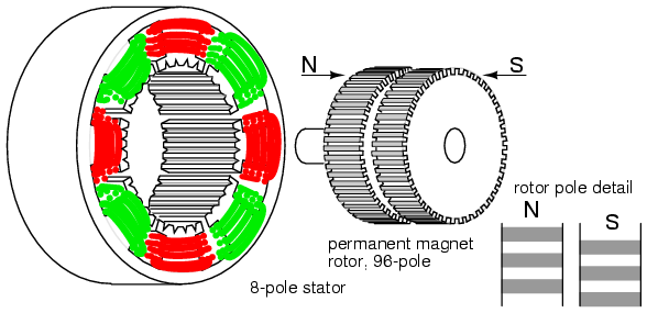
The hybrid stepper motor combines features of both the variable reluctance stepper and the permanent magnet stepper to produce a smaller step angle. The rotor is a cylindrical permanent magnet, magnetized along the axis with radial soft iron teeth (Figure below). The stator coils are wound on alternating poles with corresponding teeth. There are typically two winding phases distributed between pole pairs. This winding may be center tapped for unipolar drive. The center tap is achieved by a bifilar winding, a pair of wires wound physically in parallel, but wired in series. The north-south poles of a phase swap polarity when the phase drive current is reversed. Bipolar drive is required for un-tapped windings.
Hybrid stepper motor.
Note that the 48-teeth on one rotor section are offset by half a pitch from the other. See rotor pole detail above. This rotor tooth offset is also shown below. Due to this offset, the rotor effectively has 96 interleaved poles of opposite polarity. This offset allows for rotation in 1/96 th of a revolution steps by reversing the field polarity of one phase. Two phase windings are common as shown above and below. Though, there could be as many as five phases.
The stator teeth on the 8-poles correspond to the 48-rotor teeth, except for missing teeth in the space between the poles. Thus, one pole of the rotor, say the south pole, may align with the stator in 48 distinct positions. However, the teeth of the south pole are offset from the north teeth by half a tooth. Therefore, the rotor may align with the stator in 96 distinct positions. This half tooth offset shows in the rotor pole detail above, or Figure below.
As if this were not complicated enough, the stator main poles are divided into two phases (φ-1, φ-2). These stator phases are offset from one another by one-quarter of a tooth. This detail is only discernable on the schematic diagrams below. The result is that the rotor moves in steps of a quarter of a tooth when the phases are alternately energized. In other words, the rotor moves in 2×96=192 steps per revolution for the above stepper.
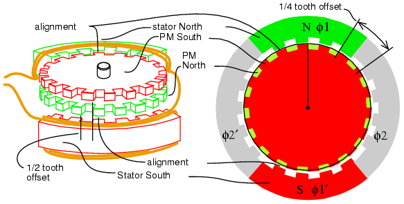
The above drawing is representative of an actual hybrid stepper motor. However, we provide a simplified pictorial and schematic representation (Figure below) to illustrate details not obvious above. Note the reduced number of coils and teeth in rotor and stator for simplicity. In the next two figures, we attempt to illustrate the quarter tooth rotation produced by the two stator phases offset by a quarter tooth, and the rotor half tooth offset. The quarter tooth stator offset in conjunction with drive current timing also defines direction of rotation.
Hybrid stepper motor schematic diagram.
- The top of the permanent magnet rotor is the south pole, the bottom north.
- The rotor north-south teeth are offset by half a tooth.
- If the φ-1 stator is temporarily energized north top, south bottom.
- The top φ-1 stator teeth align north to rotor top south teeth.
- The bottom φ-1’ stator teeth align south to rotor bottom north teeth.
- Enough torque applied to the shaft to overcome the hold-in torque would move the rotor by one tooth.
- If the polarity of φ-1 were reversed, the rotor would move by one-half tooth, direction unknown. The alignment would be south stator top to north rotor bottom, north stator bottom to south rotor.
- The φ-2 stator teeth are not aligned with the rotor teeth when φ-1 is energized. In fact, the φ-2 stator teeth are offset by one-quarter tooth. This will allow for rotation by that amount if φ-1 is de-energized and φ-2 energized. Polarity of φ-1 and drive determines direction of rotation.
Hybrid stepper motor rotation sequence.
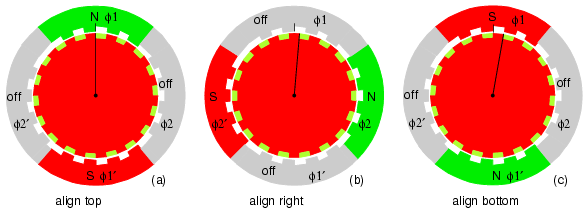
Hybrid stepper motor rotation (Figure above)
- Rotor top is permanent magnet south, bottom north. Fields φ1, φ-2 are switchable: on, off, reverse.
- (a) φ-1=on=north-top, φ-2=off. Align (top to bottom): φ-1 stator-N:rotor-top-S, φ-1’ stator-S: rotor-bottom-N. Start position, rotation=0.
- (b) φ-1=off, φ-2=on. Align (right to left): φ-2 stator-N-right:rotor-top-S, φ-2’ stator-S: rotor-bottom-N. Rotate 1/4 tooth, total rotation=1/4 tooth.
- (c) φ-1=reverse(on), φ-2=off. Align (bottom to top): φ-1 stator-S:rotor-bottom-N, φ-1’ stator-N:rotor-top-S. Rotate 1/4 tooth from last position. Total rotation from start: 1/2 tooth.
- Not shown: φ-1=off, φ-2=reverse(on). Align (left to right): Total rotation: 3/4 tooth.
- Not shown: φ-1=on, φ-2=off (same as (a)). Align (top to bottom): Total rotation 1-tooth.
An un-powered stepper motor with detent torque is either a permanent magnet stepper or a hybrid stepper. The hybrid stepper will have a small step angle, much less than the 7.5o of permanent magnet steppers. The step angle could be a fraction of a degree, corresponding to a few hundred steps per revolution.
Summary: hybrid stepper motor
- The step angle is smaller than variable reluctance or permanent magnet steppers.
- The rotor is a permanent magnet with fine teeth. North and south teeth are offset by half a tooth for a smaller step angle.
- The stator poles have matching fine teeth of the same pitch as the rotor.
- The stator windings are divided into no less than two phases.
- The poles of one stator windings are offset by a quarter tooth for an even smaller step angle.