So far, we’ve explored tubes which are totally “evacuated” of all gas and vapor inside their glass envelopes, properly known as vacuum tubes. With the addition of certain gases or vapors, however, tubes take on significantly different characteristics, and are able to fulfill certain special roles in electronic circuits.
When a high enough voltage is applied across a distance occupied by a gas or vapor, or when that gas or vapor is heated sufficiently, the electrons of those gas molecules will be stripped away from their respective nuclei, creating a condition of ionization. Having freed the electrons from their electrostatic bonds to the atoms’ nuclei, they are free to migrate in the form of a current, making the ionized gas a relatively good conductor of electricity. In this state, the gas is more properly referred to as a plasma.
Ionized gas is not a perfect conductor. As such, the flow of electrons through ionized gas will tend to dissipate energy in the form of heat, thereby helping to keep the gas in a state of ionization. The result of this is a tube that will begin to conduct under certain conditions, then tend to stay in a state of conduction until the applied voltage across the gas and/or the heat-generating current drops to a minimum level.
The astute observer will note that this is precisely the kind of behavior exhibited by a class of semiconductor devices called “thyristors,” which tend to stay “on” once turned “on” and tend to stay “off” once turned “off.” Gas-filled tubes, it can be said, manifest this same property of hysteresis.
Unlike their vacuum counterparts, ionization tubes were often manufactured with no filament (heater) at all. These were called cold-cathode tubes, with the heated versions designated as hot-cathode tubes. Whether or not the tube contained a source of heat obviously impacted the characteristics of a gas-filled tube, but not to the extent that lack of heat would impact the performance of a hard-vacuum tube.
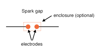
The simplest type of ionization device is not necessarily a tube at all; rather, it is constructed of two electrodes separated by a gas-filled gap. Simply called a spark gap, the gap between the electrodes may be occupied by ambient air, other times a special gas, in which case the device must have a sealed envelope of some kind.

A prime application for spark gaps is in overvoltage protection. Engineered not to ionize, or “break down” (begin conducting), with normal system voltage applied across the electrodes, the spark gap’s function is to conduct in the event of a significant increase in voltage. Once conducting, it will act as a heavy load, holding the system voltage down through its large current draw and subsequent voltage drop along conductors and other series impedances. In a properly engineered system, the spark gap will stop conducting (“extinguish”) when the system voltage decreases to a normal level, well below the voltage required to initiate conduction.
One major caveat of spark gaps is their significantly finite life. The discharge generated by such a device can be quite violent, and as such will tend to deteriorate the surfaces of the electrodes through pitting and/or melting.
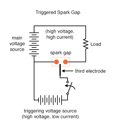
Spark gaps can be made to conduct on command by placing a third electrode (usually with a sharp edge or point) between the other two and applying a high voltage pulse between that electrode and one of the other electrodes. The pulse will create a small spark between the two electrodes, ionizing part of the pathway between the two large electrodes, and enabling conduction between them if the applied voltage is high enough:

Spark gaps of both the triggered and untriggered variety can be built to handle huge amounts of current, some even into the range of mega-amps (millions of amps)! Physical size is the primary limiting factor to the amount of current a spark gap can safely and reliably handle.
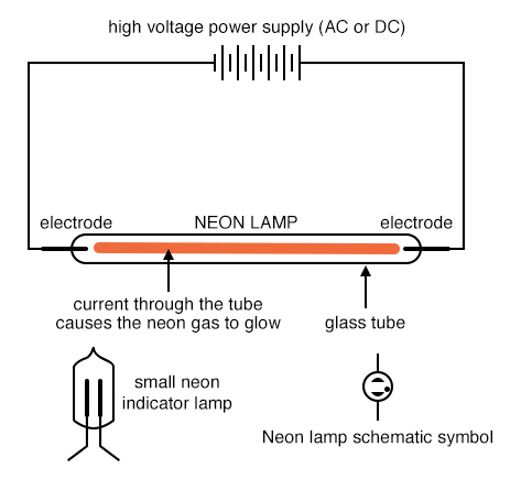
When the two main electrodes are placed in a sealed tube filled with a special gas, a discharge tube is formed. The most common type of discharge tube is the neon light, used popularly as a source of colorful illumination, the color of the light emitted being dependent on the type of gas filling the tube.
Construction of neon lamps closely resembles that of spark gaps, but the operational characteristics are quite different:

By controlling the spacing of the electrodes and the type of gas in the tube, neon lights can be made to conduct without drawing the excessive currents that spark gaps do. They still exhibit hysteresis in that it takes a higher voltage to initiate conduction than it does to make them “extinguish,” and their resistance is definitely nonlinear (the more voltage applied across the tube, the more current, thus more heat, thus lower resistance). Given this nonlinear tendency, the voltage across a neon tube must not be allowed to exceed a certain limit, lest the tube be damaged by excessive temperatures.
This nonlinear tendency gives the neon tube an application other than colorful illumination: it can act somewhat like a zener diode, “clamping” the voltage across it by drawing more and more current if the voltage decreases. When used in this fashion, the tube is known as a glow tube, or voltage-regulator tube, and was a popular means of voltage regulation in the days of electron tube circuit design.

Please take note of the black dot found in the tube symbol shown above (and in the neon lamp symbol shown before that). That marker indicates the tube is gas-filled. It is a common marker used in all gas-filled tube symbols.
One example of a glow tube designed for voltage regulation was the VR-150, with a nominal regulating voltage of 150 volts. Its resistance throughout the allowable limits of current could vary from 5 kΩ to 30 kΩ, a 6:1 span. Like zener diode regulator circuits of today, glow tube regulators could be coupled to amplifying tubes for better voltage regulation and higher load current ranges.
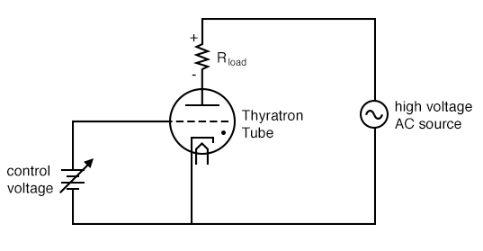
If a regular triode was filled with gas instead of a hard vacuum, it would manifest all the hysteresis and nonlinearity of other gas tubes with one major advantage: the amount of voltage applied between grid and cathode would determine the minimum plate-to cathode voltage necessary to initiate conduction. In essence, this tube was the equivalent of the semiconductor SCR (Silicon-Controlled Rectifier), and was called the thyratron.

It should be noted that the schematic shown above is greatly simplified for most purposes and thyratron tube designs. Some thyratrons, for instance, required that the grid voltage switch polarity between their “on” and “off” states in order to properly work. Also, some thyratrons had more than one grid!
Thyratrons found use in much the same way as SCR’s find use today: controlling rectified AC to large loads such as motors. Thyratron tubes have been manufactured with different types of gas fillings for different characteristics: inert (chemically non-reactive) gas, hydrogen gas, and mercury (vaporized into a gas form when activated). Deuterium, a rare isotope of hydrogen, was used in some special applications requiring the switching of high voltages.