On a fundamental level, pressure is universal. Regardless of the fluid in question; liquid or gas, hot or cold, corrosive or inert, pressure is nothing more than the amount of force exerted by that fluid over a unit area:

It should come as no surprise, then, that the common mechanical sensing elements for measuring pressure (bellows, diaphragm, bourdon tube, etc.) are equally applicable to all fluid pressure measurement applications, at least in principle. It is normally a matter of proper material selection and element strength (material thickness) to make a pressure instrument suitable for any range of process fluids.
Fill fluids used in pressure instruments – whether it be the dielectric liquid inside a differential capacitance sensor, the fill liquid of a remote or chemical seal system, or liquid used to fill a vertical section of impulse tubing – must be chosen so as to not adversely react with or contaminate the process.
Pure oxygen processes require that no system component have traces of hydrocarbon fluids present. While oxygen itself is not explosive, it greatly accelerates the combustion and explosive potential of any flammable substance. Therefore, a pressure gauge calibrated using oil as the working fluid in a deadweight tester would definitely not be suitable for pure oxygen service! The same may be said for a DP transmitter with a hydrocarbon-based fill inside its pressure-sensing capsule30 .
Pharmaceutical, medical, and food manufacturing processes require strict purity and the ability to disinfect all elements in the process system at will. Stagnant lines are not allowed in such processes, as microbe cultures may flourish in such “dead end” piping. Remote seals are very helpful in overcoming this problem, but the fill fluids used in remote systems must be chosen such that a leak in the isolating diaphragm will not contaminate the process.
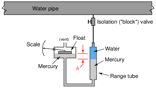
Manometers, of course, are rather limited in their application, as their operation depends on direct contact between process fluid and manometer liquid. In the early days of industrial instrumentation, liquid mercury was a very common medium for process manometers, and it was not unusual to see a mercury manometer used in direct contact with a process fluid such as oil or water to provide pressure indication:

Thankfully, those days are gone. Mercury (chemical symbol “Hg”) is a toxic metal and therefore hazardous to work with. Calibration of these manometers was also challenging due to the column height of the process liquid in the impulse line and the range tube. When the process fluid is a gas, the difference in mercury column height directly translates to sensed pressure by the hydrostatic pressure formula P = ρgh or P = γh. When the process fluid is a liquid, though, the shifting of mercury columns also creates a change in height of the process liquid column, which means the indicated pressure is a function of the height difference (h) and the difference in density between the process liquid and mercury. Consequently, the indications provided by mercury manometers in liquid pressure applications were subject to correction according to process liquid density.
19.8 Review of fundamental principles
Shown here is a partial listing of principles applied in the subject matter of this chapter, given for the purpose of expanding the reader’s view of this chapter’s concepts and of their general inter-relationships with concepts elsewhere in the book. Your abilities as a problem-solver and as a life-long learner will be greatly enhanced by mastering the applications of these principles to a wide variety of topics, the more varied the better.
- Definition of pressure: P = F A (pressure is the amount of force applied over a specified area by a fluid.
- Pascal’s principle: changes in fluid pressure are transmitted evenly throughout an enclosed fluid volume. Relevant to pressure measurement, as fluid pressure in all parts of an enclosed system will experience the same changes in pressure.
- Hydrostatic pressure: fluids having substantial weight generate pressure proportional to their density and to their vertical height (P = γh and P = ρgh). Relevant to pressure offsets generated in vertical spans of impulse or capillary tubing, causing a pressure instrument to register more or less pressure than that at the process vessel connection.
- Self-balancing pneumatic mechanisms: all self-balancing pneumatic instruments work on the principle of negative feedback maintaining a nearly constant baffle-nozzle gap. Force-balance mechanisms maintain this constant gap by balancing force against force with negligible motion, like a tug-of-war. Motion-balance mechanisms maintain this constant gap by balancing one motion with another motion, like two dancers moving in unison.
References
Beckerath, Alexander von; Eberlein, Anselm; Julien, Hermann; Kersten, Peter; and Kreutzer, Jochem, WIKA-Handbook, Pressure and Temperature Measurement, WIKA Alexander Wiegand GmbH & Co., Klingenberg, Germany, 1995.
Calkins, A.B., “Steam and Pressure Gauges”, Cassier’s Magazine, Volume 1, London, England, 1891.
“Digital Sensor Technology” (PowerPoint slideshow presentation), Yokogawa Corporation of America.
Fribance, Austin E., Industrial Instrumentation Fundamentals, McGraw-Hill Book Company, New York, NY, 1962.
Kallen, Howard P., Handbook of Instrumentation and Controls, McGraw-Hill Book Company, Inc., New York, NY, 1961.
Lipták, Béla G. et al., Instrument Engineers’ Handbook – Process Measurement and Analysis Volume I, Fourth Edition, CRC Press, New York, NY, 2003.
Patrick, Dale R. and Patrick, Steven R., Pneumatic Instrumentation, Delmar Publishers, Inc., Albany, NY, 1993.
“Rosemount 1199 Diaphragm Seal Systems”, product data sheet 00813-0100-4016 revision HA, Rosemount, Emerson Process Management, January 2008.
Technical Note: “Rosemount 1199 Fill Fluid Specifications”, Rosemount, Emerson Process Management, 2005.